Bernie Docs
An open source SPRI beads cleanup robot

An open source SPRI beads cleanup robot
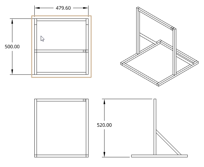
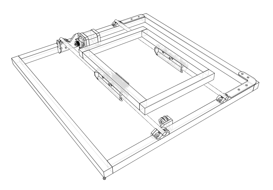
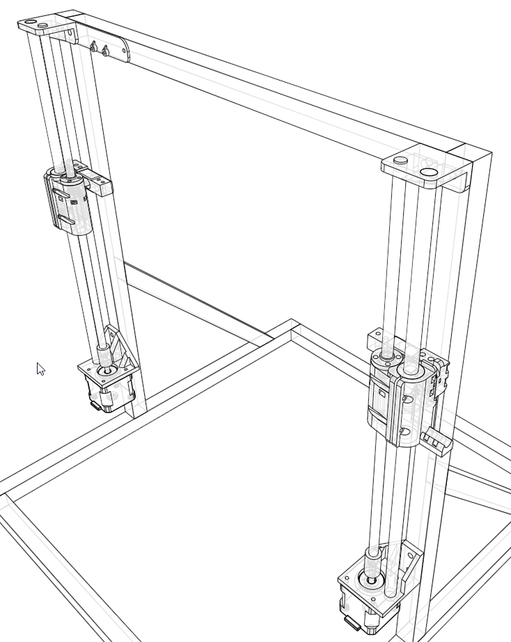
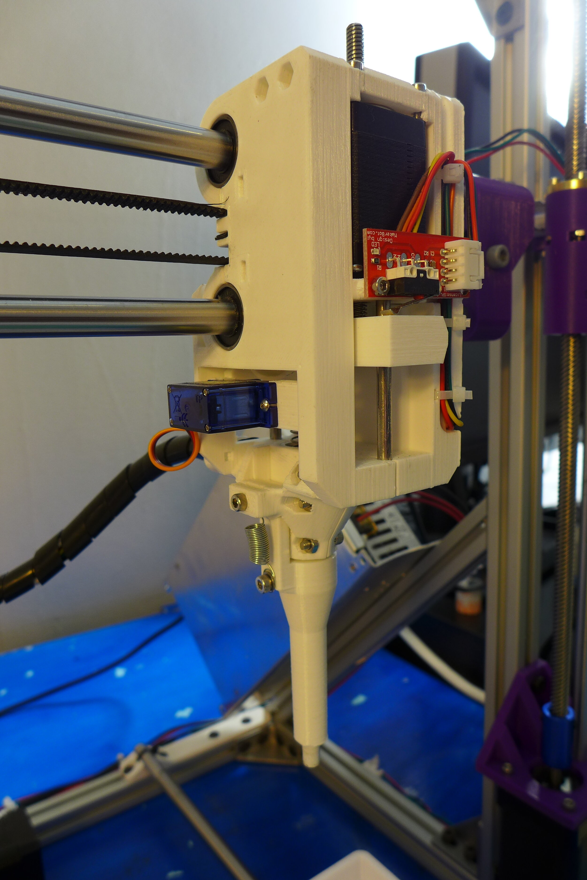
Robot’s frame is constructed from standard “8020” T-shape aluminum extrusions sized 20x20 mm.
The following parts are used:
2 bars for robot base
3 bars: 2 for robot base and one for the top.
2 diagonal bars
4 smaller bars forms the working area
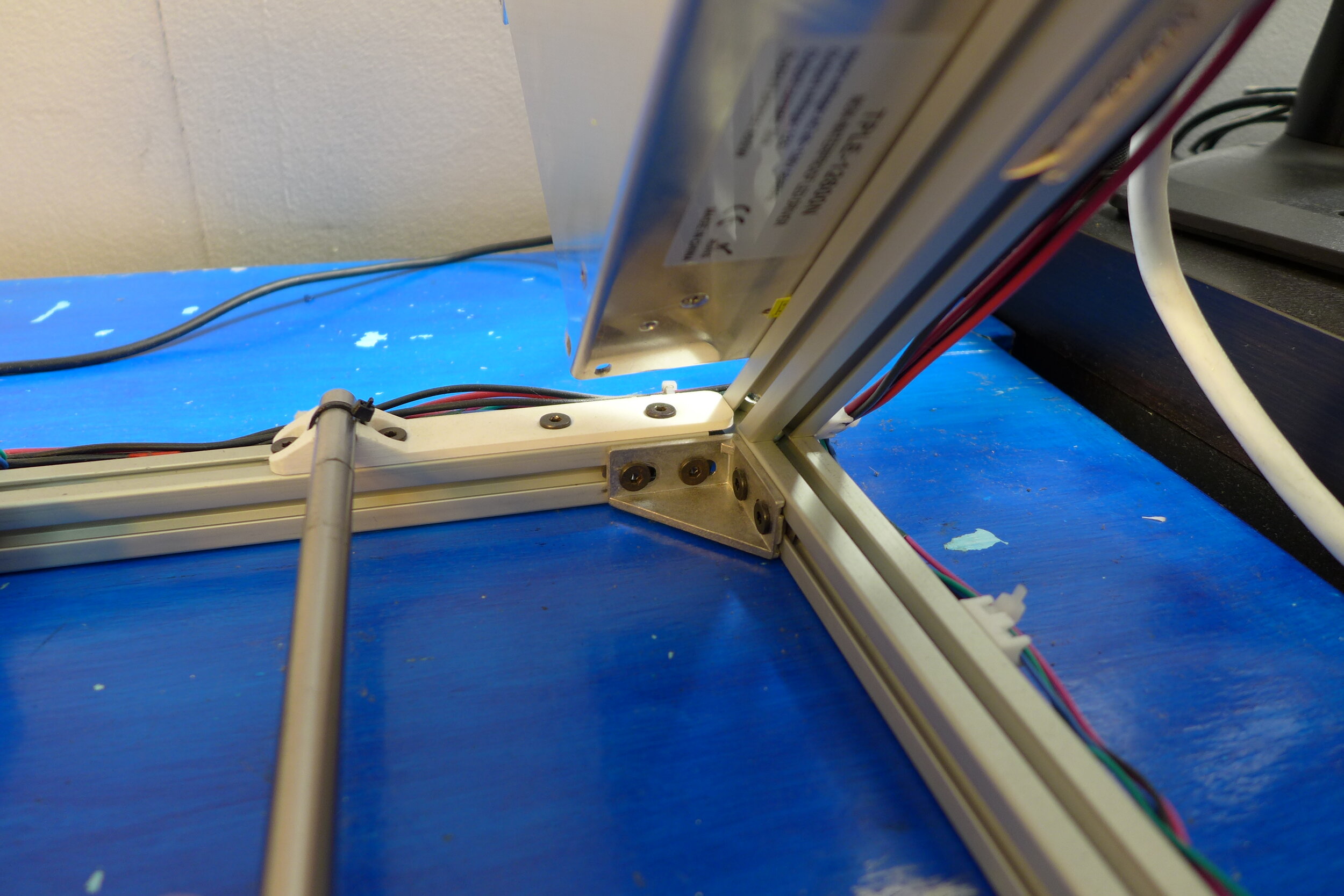
Bars are connected with the triangles.
M5 screws and nuts are used to assemble the frame.
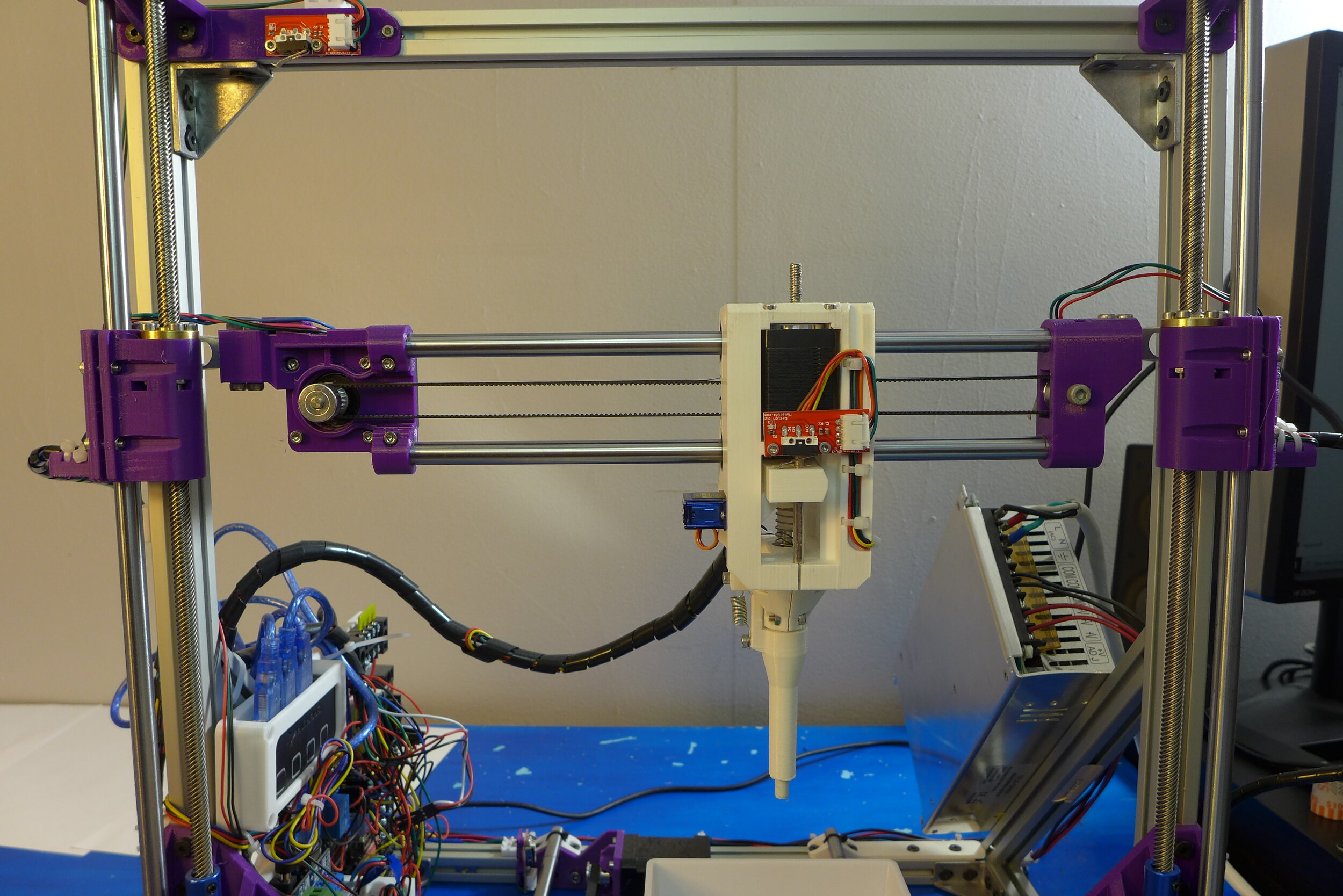
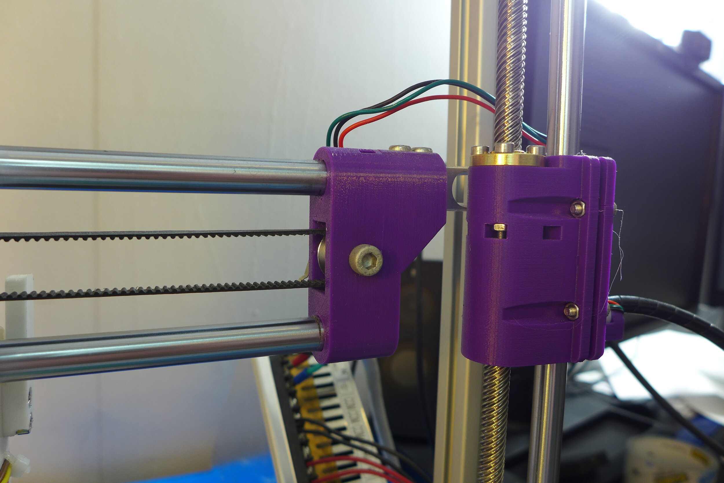
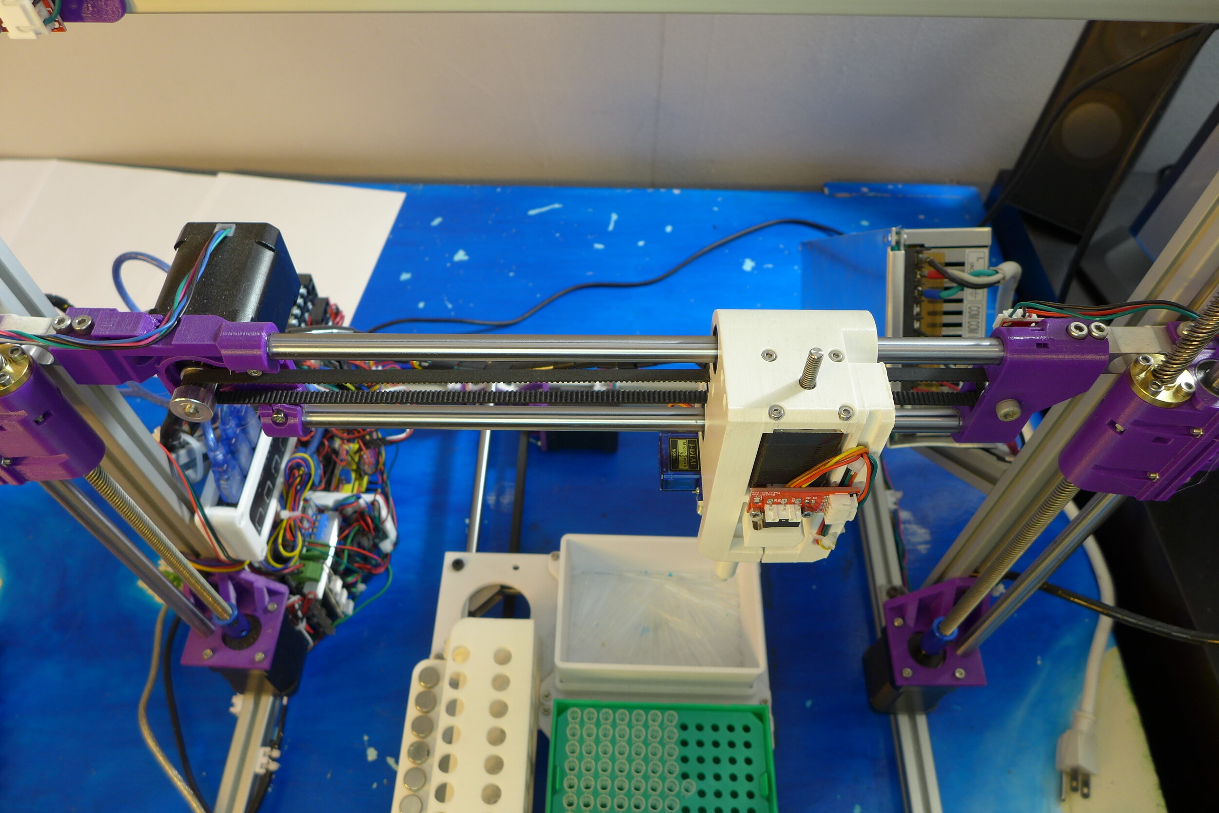
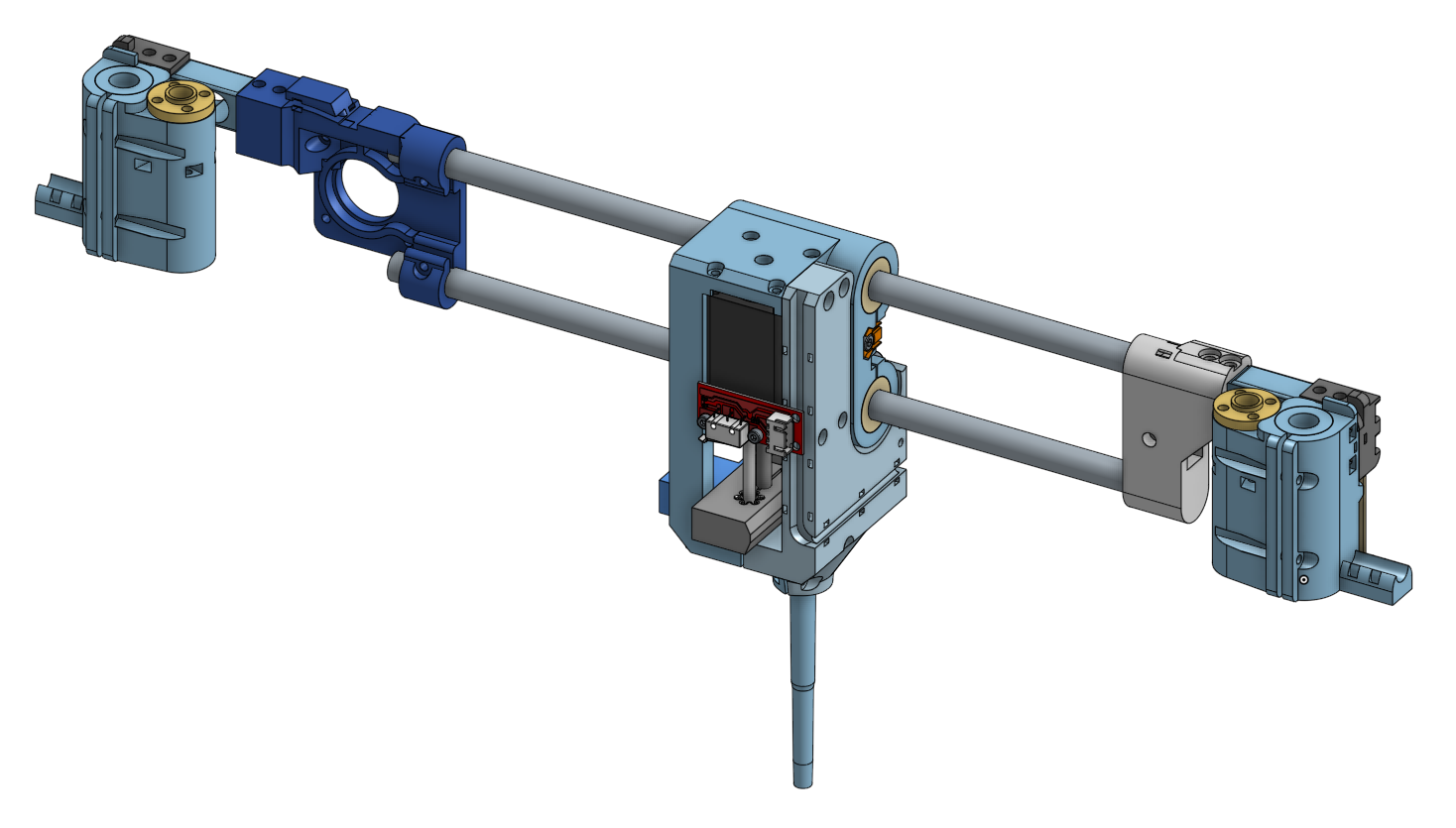
X axis consists of two linear beams of 10 mm diameter. They are holding the pipette tool. On the sides, they are connected to the left and right Z axis sliders through the load sensors.
On the left side the NEMA17 stepper motor is mounted, that is moving pipette along X axis. On the right side, the idle pulley is mounted. The pipette tool is connected to the motor pulley through the timing belt of 2mm pitch, 6 mm width.
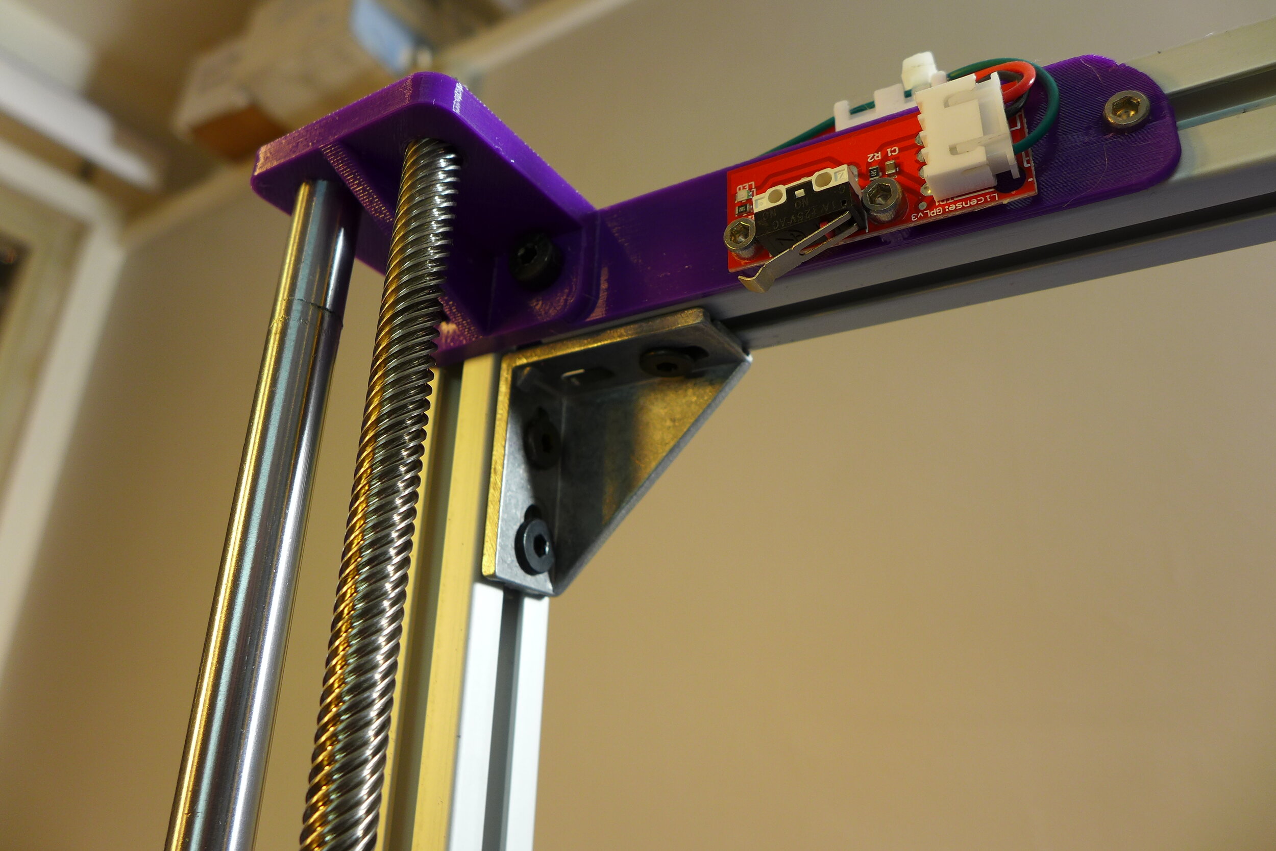
On the right side, there is an end stop switch.
When the pipette tool is at the rightmost position, it triggers the end stop switch. At that position, it is assumed to have X coordinate = 0.
Pipette tool can travel through the X axis from position 0 (rightmost) to position 200 (leftmost).
The wiring from the motor and from the end stop switch is passed to the Z axis slider.
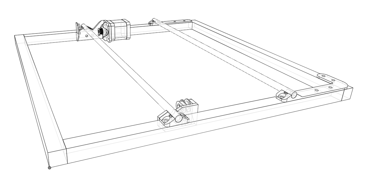
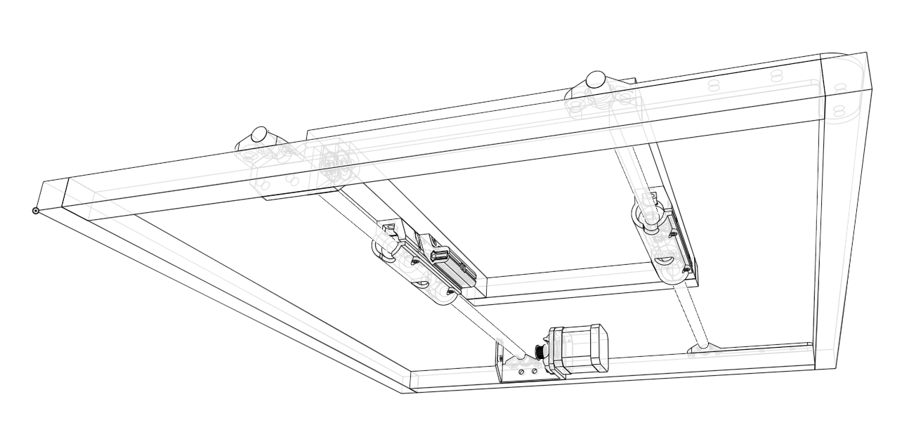
Y axis is also based on linear guide rails of 10 mm diameter. Along those rails, working area freely moves in the direction forward-backward. Working area is attached to the rails through the four linear bearings of 10 mm inner diameter.
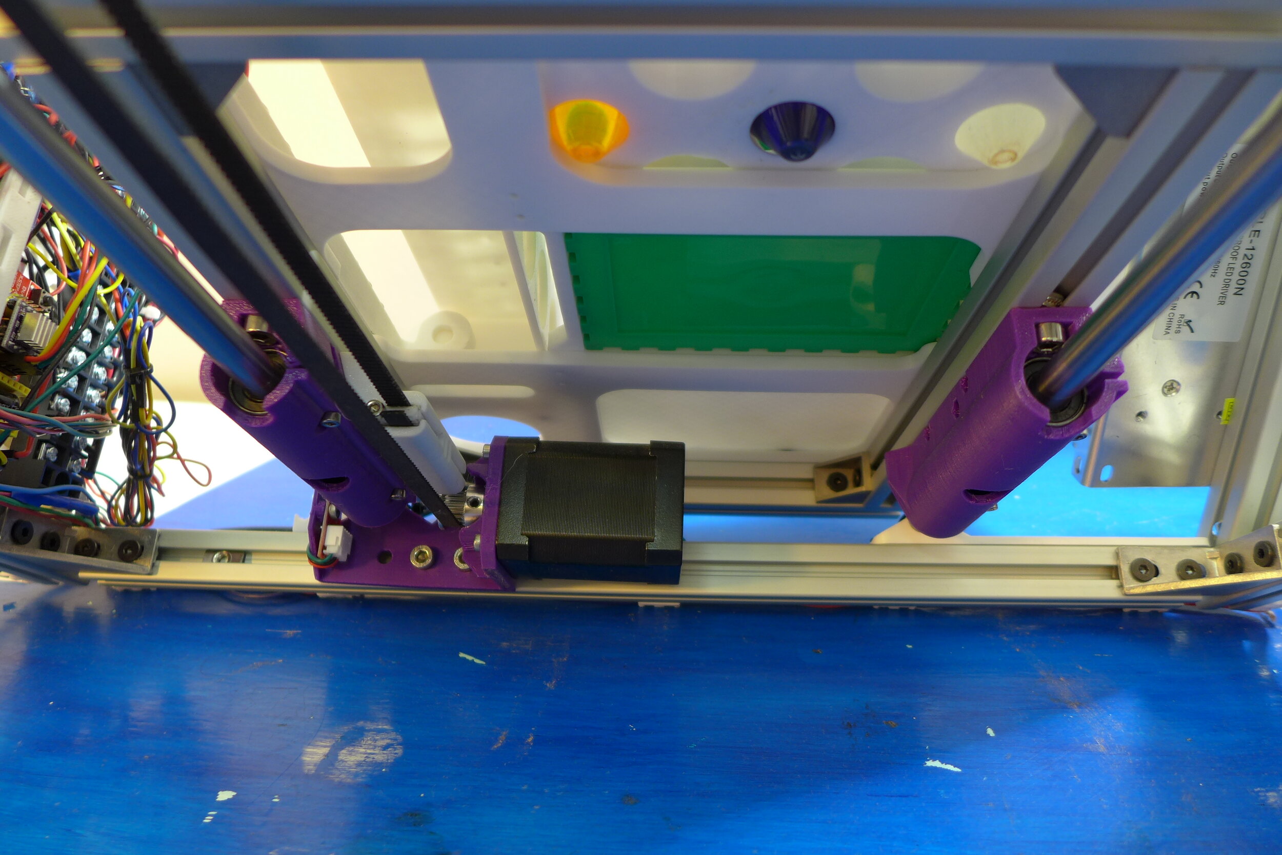
NEMA 17 stepper motor moves the working area. The movement is done with the timing belt that is anchored to the working area and passes through the idle pulley at the front and through the motor pulley at the back.
Near the stepper motor, there is an end stop switch. When working area moves to the back, the end stop switch is triggered. At this position, Y axis coordinate = 0.
Working area can move from position 0 (at the back) to position 300 (at the front).
The wiring from the motor and from the end stop switch is passed through the frame to the electronics.
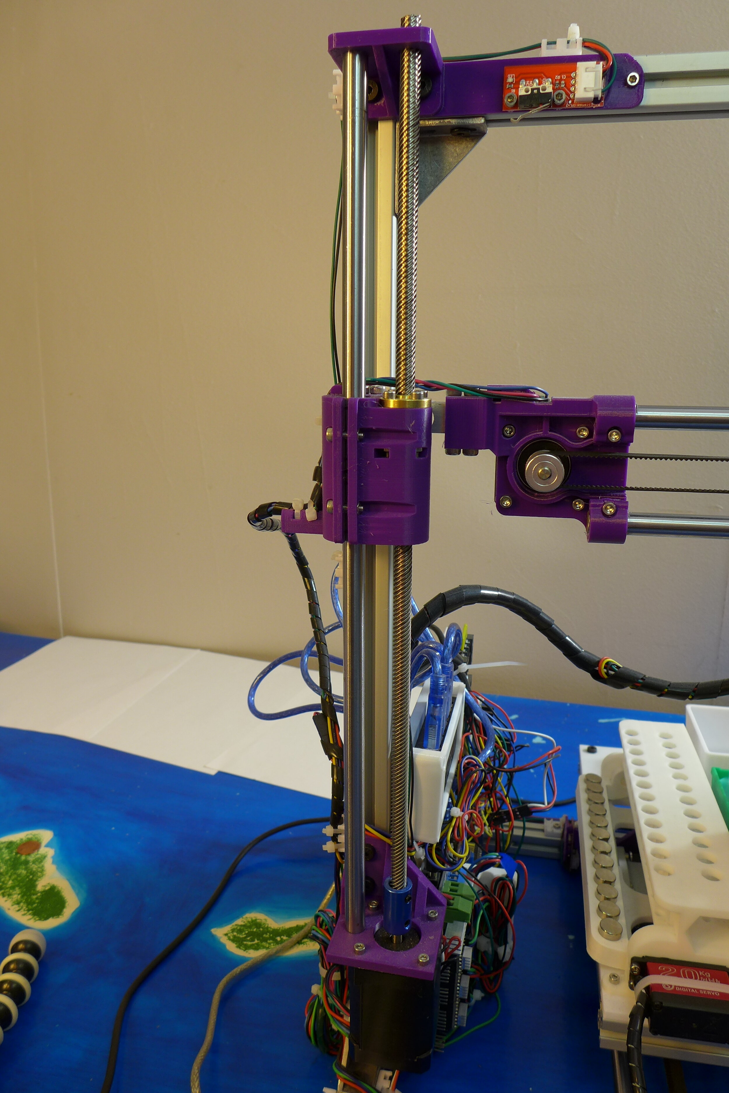
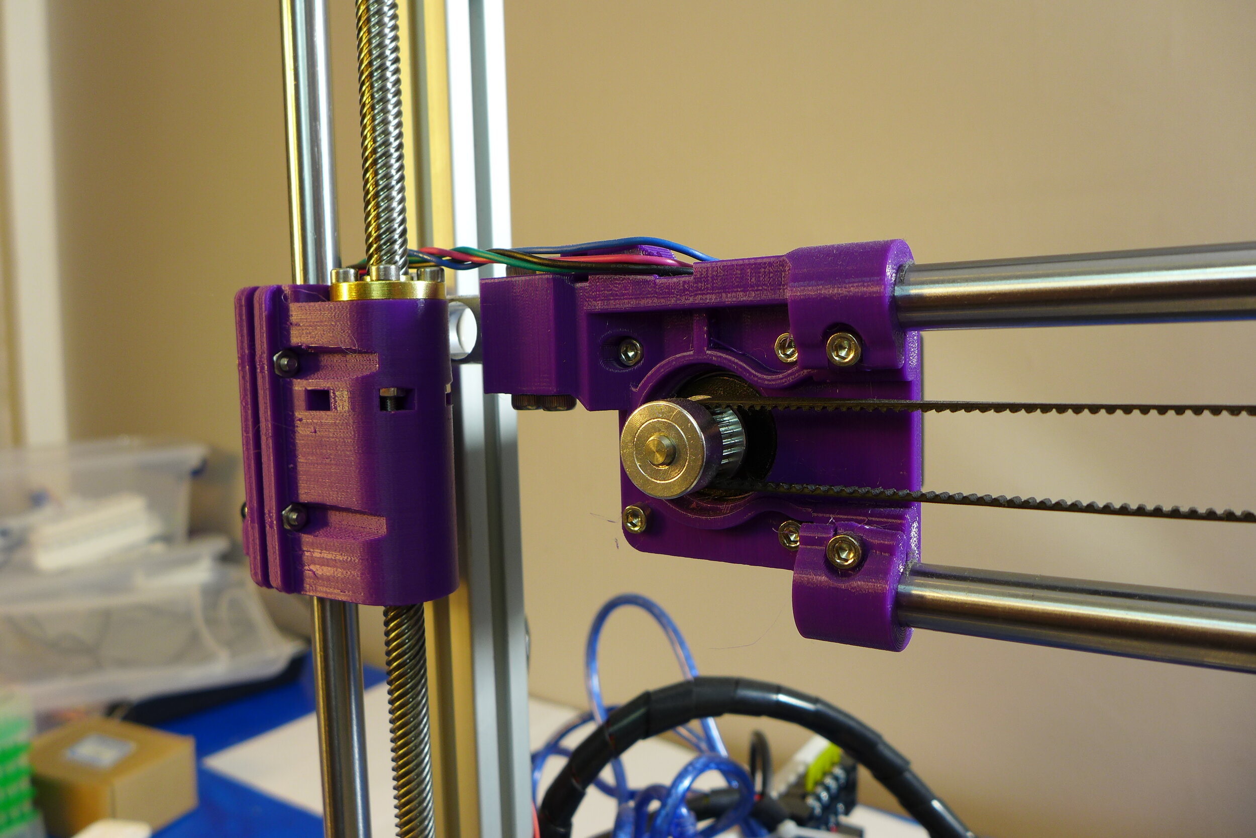
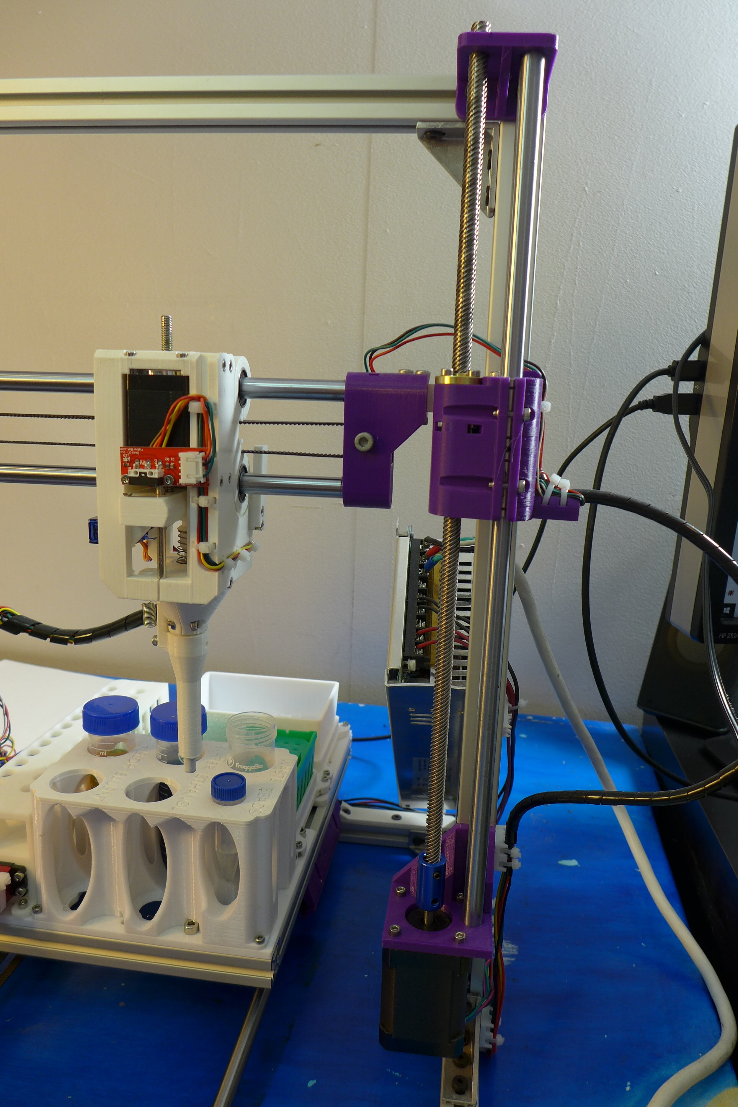
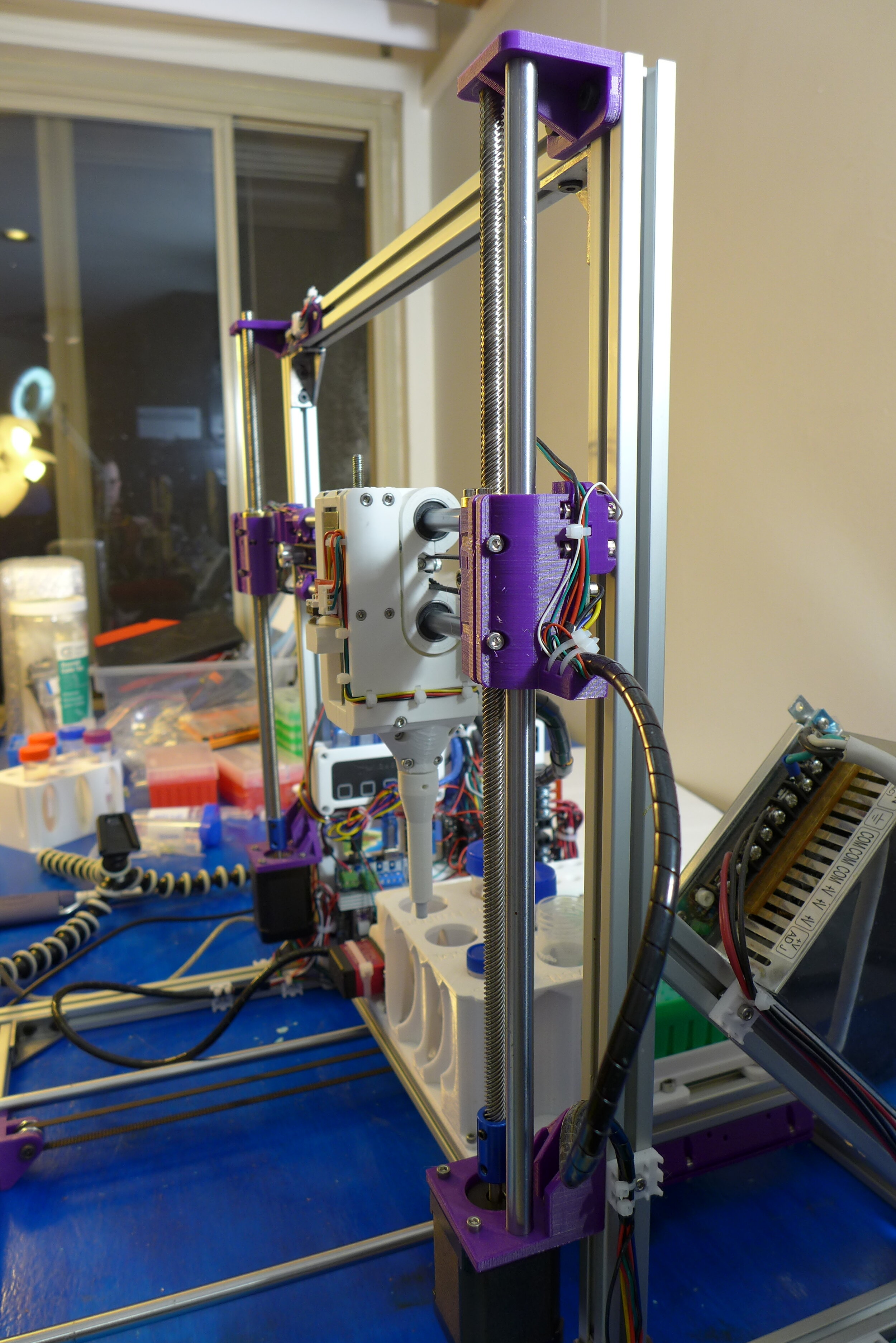
Z axis, or a vertical axis, is based on a pair of linear guide rails of 10 mm diameter. Parallel to the guide rails, there is a T8 lead screw with lead 16 mm. The Z axis sliders are attached to the guide rails through the two linear bearings each. The sliders are also attached to the T8 nut that transfers rotary movement of a lead screw to the vertical movement.
The Z-axis sliders are attached to the X axis gantry through the pair of load sensors. In the occasion when the pipette presses against something, the load is transferred through the pipette to the X axis gantry and to the load sensors.
A pair of NEMA 17 stepper motors move the Z sliders up and down. Each motor is independently connected to the electronics board, the wiring is passed along the frame.
Both guide rails and lead screws are fixed at the top and at the bottom of the frame. At the right side, there is also an end stop switch, which triggers when the Z sliders are at the top. At this position, Z axis coordinate = 0.
The Z sliders can move from position 0 to position 180 (approximately) down.
It depends on whether you need to remove only short DNA, or both long and short DNA.
If removing only small molecules and short DNA, robot purifies 12 samples simultaneously.
If you need the two-stage process removing both short and long DNA, then robot purifies 6 samples at a time.
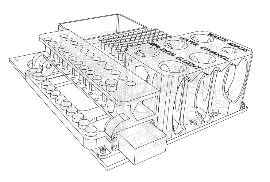
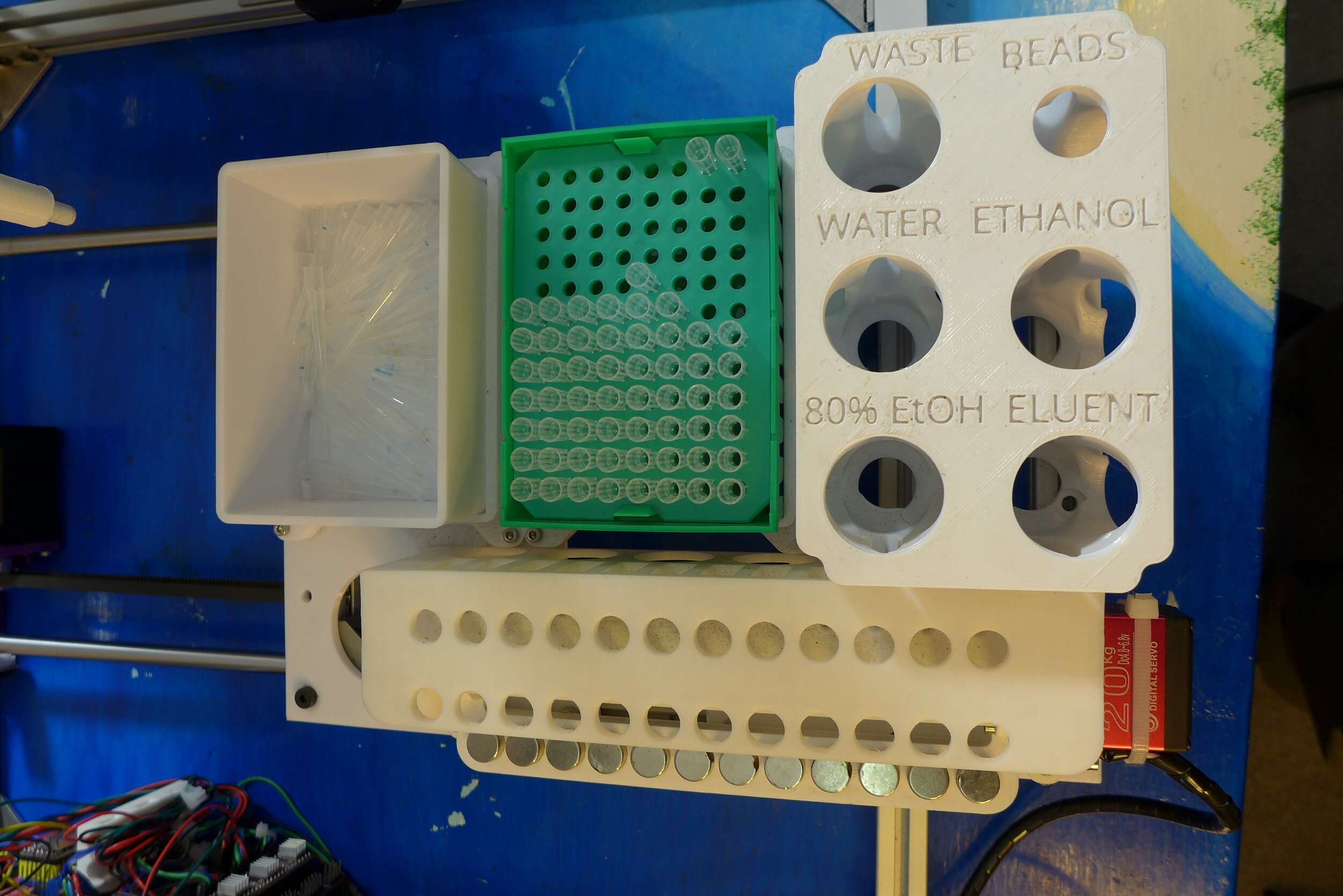
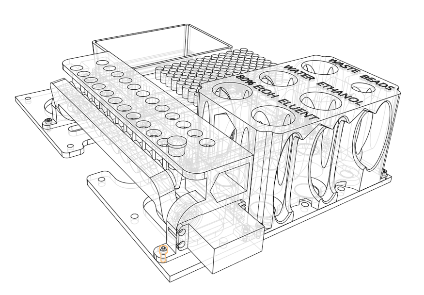
Bernie operates with samples, reagents and consumables placed in working area.
Working area consists of four different “racks”:
Samples rack
Reagents rack
Pipette tips rack
Waste rack
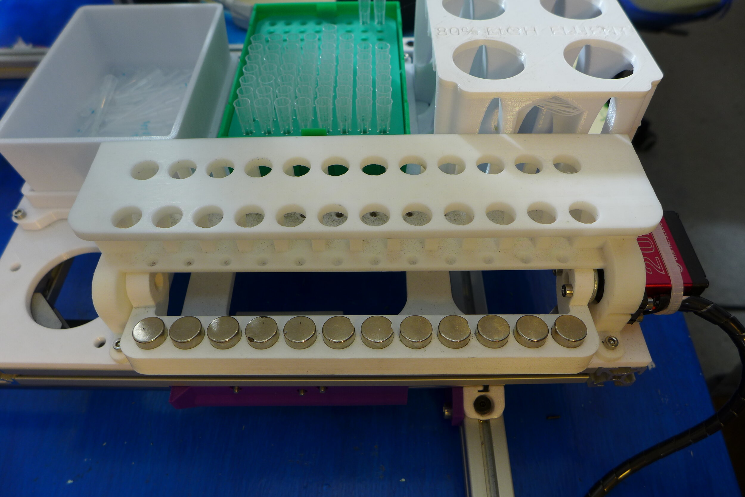
Samples rack fits 1.5 mL “Eppendorf” tubes. Samples rack is also equipped with the magnetic lever that is driven by a servo motor. The lever moves magnets either towards the samples, or away from the samples. When the lever is near the tubes, the SPRI beads are trapped near the wall of the tubes and can not be pipetted. When the lever is away from the tubes, the SPRI beads return back to the suspension and can be pipetted. The samples rack has two rows. The leftmost row, closest to the magnets lever, is for the samples that needs to be purified. The right row is for the empty tubes where the robot will move purified DNA solution.
The reagents rack has 6 positions for different reagents that may be used during purification. The positions are Waste, Water, 80% ethanol, SPRI beads, 100% ethanol, Eluent.
The pipette tips rack fits the standard Rainin tip boxes for 250 uL (they come green colored and usually used with p200 pipette). Robot will warn the user in case there is not enough tips in the box, the user is responsible to replace the boxes as needed.
The waste rack contains the waste box, where the robot drops used tips. It must be regularly emptied when full.
The working area is directly attached to the Y axis sliders and can move forward and backward with the Y axis.
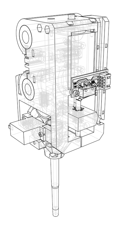
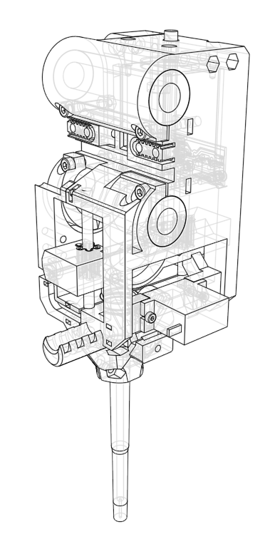
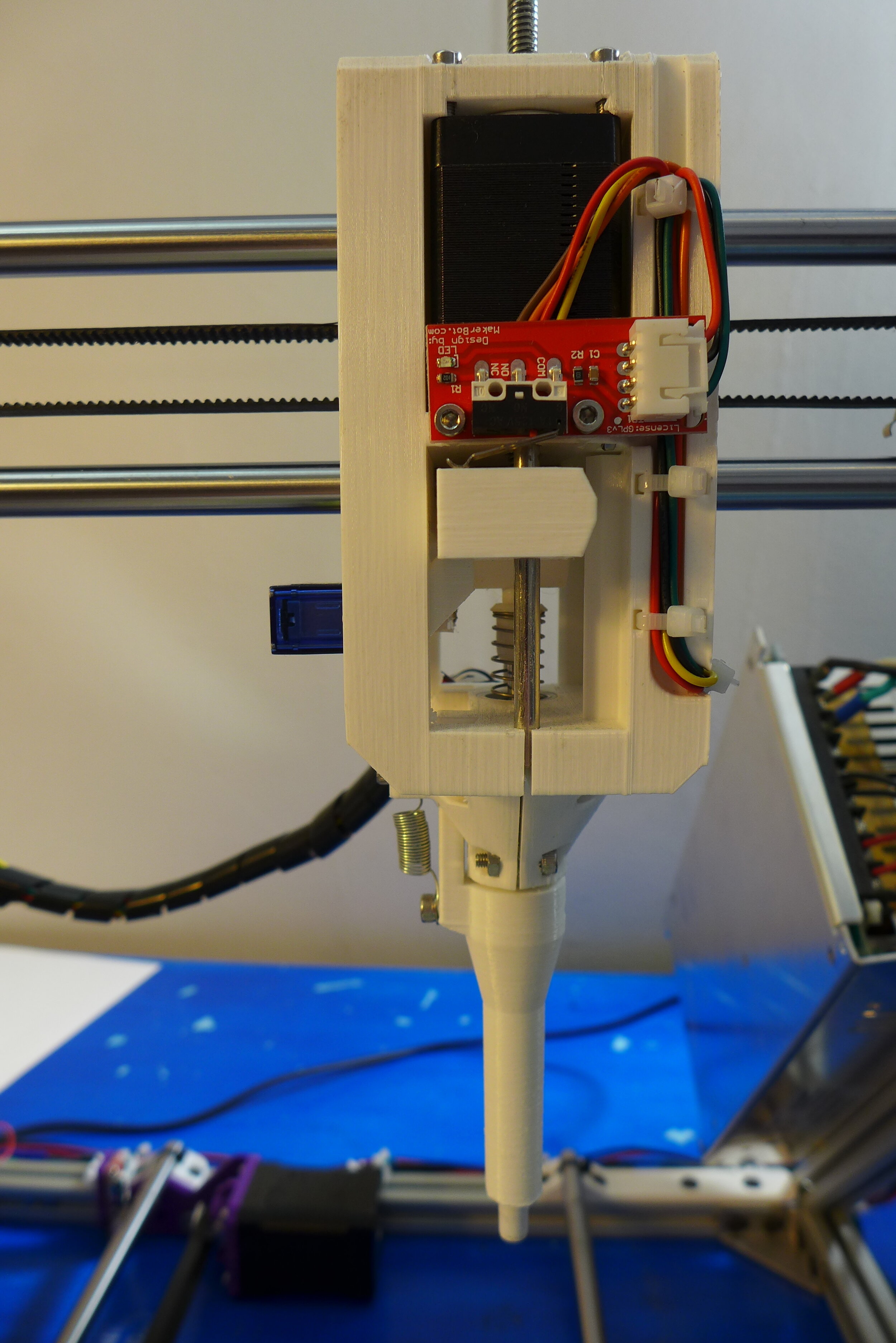
The pipetting mechanism is based on the Rainin LTS pipette L-200XLS+. The original tip attaching end and the plunger is used from the Rainin pipette. A NEMA 11 linear stepper motor is pressing on the plunger, mimicking the manual thumb pressing the button at the top of the pipette. The stepper motor has about 10 um linear resolution, which is much greater than the original volume setting mechanism. Thus, greater pipetting precision could be achieved compared to the manual pipetting.
To dispose the tip, the robot uses a small servo motor. When needed, the servo motor protrudes a horn, that is pressing on the tip disposing mechanism. The plunger is then driven down, disposing the tip.
An end stop switch is positioned to be triggered when the plunger is at uppermost position (when triggered, plunger position = 0). Plunger can move down until position = 35.
Pipette can uptake slightly more than 250 uL of liquid.
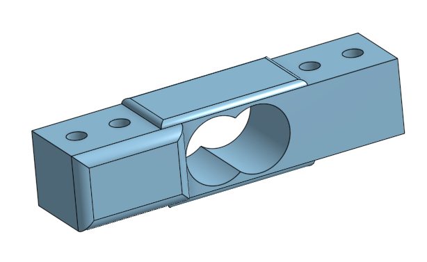
Robot is equipped with two load cells (or load sensors). The X axis gantry is attached to the Z sliders through those sensors. When robot presses on something with the pipette in the vertical direction, the load sensors output the force at which robot is pressing.
At the moment robot is using the sensors for three kind of operations.
First, when picking up a tip, robot is measuring the pressure it applies on the tip, to make sure the tip is picked up and is firmly attached. A human, when picking up a tip with a pipette, presses on it with the 3-5 kg force. The robot presses with 4 kg force when picking up a tip. In addition, right before picking up a tip, robot will measure the pressure while performing a final approach. In the case that the pipette is slightly off (tips are misaligned, or calibration is too old), the robot will attempt to right itself.
Second, when performing ethanol washes, the robot must remove all the ethanol from the sample tubes, without leaving even a smallest drop inside. Therefore, it needs to lower the tip to the very bottom of the tube. It must not be too high, otherwise it will leave some liquid in the tube. It also must not be too low, otherwise it will press against the bottom, block the tip bore and will be unable to uptake liquid at all. The precision must be less than a millimeter. Practically, it is impossible to program a precise Z coordinate of a tube bottom. Therefore, the robot will use pressure sensors to find an exact Z coordinate at which the pipette with the tip will press against the bottom.
Third, the robot uses the load sensors when performing its auto-positioning against working area racks. Robot finds an edge of each rack by sequentially tapping against the rack with the end of the pipette (without a tip). The sensors trigger when the pipette touches the rack. When the robot reaches the edge, the pipette will be able to move down without triggering the sensors. This will be understood by the software. The robot finds the center of each rack by finding its four edges. The positions of the wells are calculated based on the discovered center coordinates.
Bernie uses 4 identical NEMA 17 bipolar stepper motors for moving in X, Y and Z axes: two motors for Z axis and one for each X and Y axes. Their holding torque is 65 N*cm, 1.8 degree step angle, 200 steps/revolution, maximum current 2.1 A. Their dimensions are 42 x 42 x 60 mm.
Bernie robot moves the pipette plunger with a NEMA 11 bipolar non-captive linear stepper motor with Tr5*2 lead screw. Its holding torque is 80 mN*m, 1.8 degree step angle, resolution of 0.01 mm, maximum current 0.75 A. Its size is 28.2 x 28.2 x 43 mm.
A generic 20 kg digital servo motor with control angle 270 degrees is used.
A generic 9 g micro servo motor is used.
A standard 12 V DC 250 watt power supply is used to power the Bernie robot. The power supply is located at the right side of the robot. Power wires are passed through the frame to the controlling electronics.
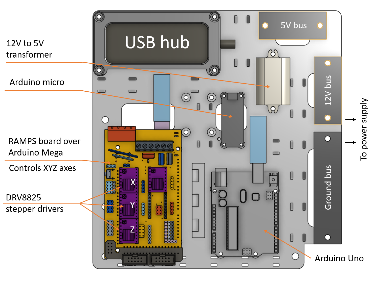
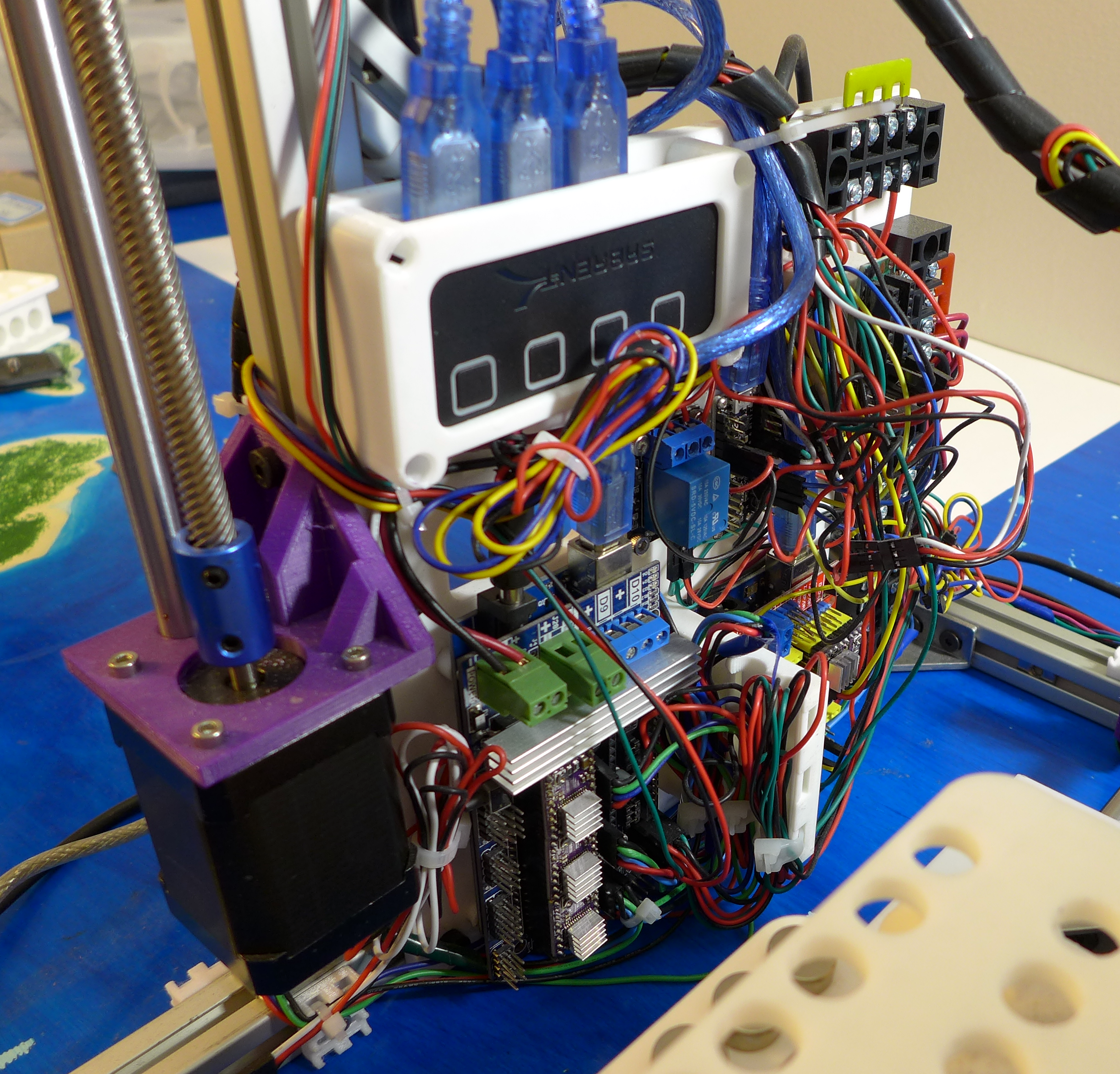
Robot controlling electronics is based on the standard Arduino boards.
Several boards are managing different Bernie operations. The operations include:
X, Y, Z axes movements. Managed by Arduino Mega board with RAMPS 1.6 board plugged in. Three DRV8825 stepper motors drivers are plugged into RAMPS board, one for each axis. Wires from X, Y and Z motors are plugged into the RAMPS board, as well as the three end stop switches for X, Y and Z axes. The Arduino Mega board runs a modified Marlin firmware. The power inlets from both Arduino Mega and RAMPS boards are connected to 12 V DC and Ground buses.
Pipette movements are managed by a separate Arduino Uno board with GRBL board plugged in. One DRV8825 stepper motor driver is plugged into the GRBL board to the X axis slot. All other stepper motor driver slots are left empty. The wires from the pipette plunger operating stepper motor are plugged into the GRBL board X axis slot. The end stop switch for the plunger is also connected to the GRBL board. The 9g micro servo for tip removal mechanism is connected to the GRBL board. The micro servo is powered through the 5V bus. The board runs a modified GRBL firmware that has the spindle functionality replaced with the servo operation functionality.
The Arduino micro board is managing the 20 kg servo for magnetic lever, as well as the load cells. The servo 5V power is connected through the relay that is also controlled by the Arduino micro boards. The board powers the motor through the relay once it needs to operate, and turns the power off once the operation is complete. This is needed to prevent the motor stalling (which will destroy the motor) or jigging (which may kick tubes and displace the beads pellets).
All three board are connected to the USB hub. The USB hub input cable is connected to the controlling computer (laptop, desktop, raspberry pi etc.).
The reason for having three different boards for Bernie control rather than one universal board is the lack of the resources to develop a custom firmware that will manage all aspects of operations. If someone is willing to donate their effort to modify either Marlin, or GRBL or other firmware so it can manage the entire robot functionality, please contact me.
When the Bernie robot is connected to a computer running Windows operation system, three serial ports will be recognized. Each Arduino board is recognized as a separate device, connected as a COM port. For example, it may be COM1, COM2, COM3. The Linux or Mac machine will use different port names. At the moment, software works only on Windows machine. The number of the COM ports may be different. When communicating with Bernie, the command must be send to a correspondent COM port.
For the simplicity, the ports will be called as an “XYZ port” for XYZ axes controller, a “pipette port” for the pipette controller and a “misc port” for the controller responsible for load sensors and magnetic lever servo motor.
The ports may be opened using an Arduino development environment (Tools -> Serial monitor), using Python Serial module or any other serial port monitor.
When opened, each controller will send a unique “greeting message”. The software is using this greeting name to map the port name to a controller, so it knows which one to send a particular message.
The XYZ port will send a standard Marlin greeting started as:
Marlin 1.1.8The XYZ port will finish each message as:
OK\n\rThe pipette port will send a following message:
Grbl Eh Servo 0.9j ['$' for help]['$H'|'$X' to unlock]If send “?” symbol, the pipette port will respond as “busy” if it still physically performing an operation or “idle” if the operation is finished.
The Misc port will send the message starting with:
Arnie's mobile gripper toolThe XYZ port will accept all the Marlin commands. However, only few are used to operate Bernie.
G28Homing command. Robot will seek end stops for all three axes.
G28 XG28 YG28 ZHome only one axis.
G0Moves specified axis.
Example:
G0 X30Will move X axis to the position 30
G0 X40 Y10 F3000Will move X axis to the position 40, Y to the position 10 at speed 3000.
$XThis command have to be send at the beginning of operation, otherwise the firmware will not execute any other command.
$HHome pipette plunger.
G0 X<position>Move pipette plunger to a position. Position may be 0-40.
M3 S<position>Move servo to a position. Position may be 10-115.
M3 S10Move servo to a position where it will not cause a tip dispatch.
M3 S115Move servo to a position at which it will cause a tip dispatch if plunger is moved down.
M3 S115G0 X40Those two commands executed sequentially will dump an attached pipette tip.
?Will make pipette controlling firmware to return its status; specifically, whether it is still physically executing a command, or it is done with execution and waiting.
TTare both load sensors. If read is taken after this command, both sensors should return 0.
RRRead the value of the right load sensor (one near the X motor)
RLRead the value of the left load sensor (one near power supply)
P onPower the servo motor that moves the magnetic lever
P offPower off the servo motor that moves the magnetic lever
G0 <angle>Moves the magnetic lever to a specific angle
G0 40Move the magnets away from the tubes
G0 93Move the magnets to the tubes
This is a preliminary library documentation. Full documentation will be released at the end of the crowdfunding campaign.
import bernielibrobot = bernielib.robot()Initialize the robot instance.
response = robot.writeAndWaitPipette(expression, confirm_message="Idle")Send a command to the pipette firmware. Expression is a firmware command in string format. confirm_message is the firmware reply indicating that the physical execution is complete.
response = robot.writeAndWaitCartesian(expression)Send a command to the XYZ controlling firmware.
response = robot.writeAndWaitMisc(self, expression)Send a command to the Misc firmware.
robot.pipetteHome()Home the pipette
robot.pipetteMove()Move pipette to an absolute position
robot.pipetteServoUp()Move the tip dispatching servo to a position at which it will not discard a tip.
robot.pipetteServoDown()Move the servo to a position at which the plunger will discard a tip.
robot.pickUpTip(column, row, fine_approach_dz=12.5, raise_z=0, raise_dz_with_tip=60, dx=0, dy=0)Pick up a tip from a specific position. column, row encode a coordinates of the tip. Valid column values are 0-11, valid row values are 0-7. fine_approach_dz indicates how far from the tip rack to start a fine approach. Fine approach is the sequential iterative movement while measuring the values of load sensors. Once values are greater than provided in the settings, the approach is done. If load sensors are triggered out of expected Z coordinate range (robot missed a tip and hit its edge), the procedure for tip search is initiated.
robot.pickUpNextTip()Pickup a next available tip (according to the robot’s records).
robot.dumpTip()Discard an attached tip at the current robot position.
robot.dumpTipToWaste()Move the XYZ coordinates so the pipette is above the waste rack. Then, discard the tip.
robot.dumpTipToPosition(column, row)Dumps the tip to the tip rack, to the specified column and row.
robot.returnTipBack()Returns the attached tip to the tip rack, to the same position as it was picked up from.
robot.movePipetteToVolume(volume)Moves the plunger to a position, that will push the certain volume from the tip.
robot.uptakeLiquid(sample, volume, v_insert_override=None, lag_vol=5, dry_tube=False, in_place=False)Uptake liquid of certain volume.
v_insert_override: If specified, the robot will insert the tip to this volume, ignoring everything else. Specifying 0 will get to the perceived bottom of the tube. lag_vol: To compensate for the plunger lag, the robot will uptake a little more liquid, and then release it back. Default 5. Specify 0 to turn it off. In case there is not enough liquid, robot will automatically turn it off. dry_tube: Provide True to command the robot to perform special procedure to make sure that all liquid is out of the tube. Only makes sense if the volume in the tube is <= uptake volume. Otherwise robot will automatically turn it back to False. in_place: If True, the robot will uptake liquid right where it is, without adjusting XYZ coordinates.
robot.dispenseLiquid(sample, volume, extra_vol_insert=100, in_place=False, plunger_retract=True, blow_extra=False, move_up_after=True)Dispenses liquid of a certain volume from pipettor into specified sample. extra_vol_insert: Level at which the pipette will be inserted into the tube, relative to the sample top. For example, if total maximum volume of a tube is 1700 uL, then value 100 will make robot insert the tip to the level of 1600 uL. in_place: If True, will dispence liquid right where the robot currently is, without adjusting any coordinate. plunger_retract: After pipetting, plunger will be retracted to 0. blow_extra: After pipetting, robot will move plunger down all the way, to remove all possible leftover liquid in the tip. move_up_after: If true, robot will move up to the top of the tube after pipetting.
robot.touchWall(sample, V_touch=None, touch_liquid=False, x=0, y=0, z=None, move_up_after=False)Touches the wall of the sample. After pipetting, there might be a liquid drop hanging on the tip. This allows to touch a tube, so the drop is left on it. V_touch: Level in the tube, at which the touch will be performed, uL. touch_liquid: If True, the liquid will be touched instead of the wall. V_touch parameter is ignored. Default is False. x, y: Coordinates relative to the tube center at which the touch will be performed. If 0 (default), the touch coordinates will be calculated from the tube inner diameter. If any coordinate is provided, that will be the coordinate at which touching is performed. z: Z coordinate at which to perform touching, relative to the top of the tube. Default is None, in which case the V_touch is used to calculate Z coordinate. Positive value means inside the tube; 0 means at the top of the tube. Negative values are forbidden. Overrides specified V_touch or touch_liquid parameter.
robot.transferLiquid(source, destination, volume, lag_vol=5, dry_tube=False, v_immerse_dispense=100, touch_wall=True, safe_z=50)Transfer certain volume of a liquid from one source tube to the other destination tube. Extra air will be blown to the destination tube to ensure all the liquid from the tip gets to the tube. lag_vol: The extra volume that robot will intake and dispense back to the source sample to account for mechanical movement lag. dry_tube: If True, will attempt to remove all liquid from the source. Default False. v_immerse_dispense: Volume mark at the destination tube at which liquid will be dispensed. touch_wall: When pipetting, robot will touch wall of a destination tube to drop a remaining liquid. safe_z: When transferring, robot will lift Z axis to that absolute value.
robot.robotHome()Home XYZ axes.
robot.home()Home all robot axes and pipette plunger, moves magnets away from the tubes.
robot.move(x=None, y=None, z=None, z_first=True, speed_xy=None, speed_z=None)Move the XYZ axes to a new position using absolute coordinates x, y and z. Any x, y, z are optional. z_first: If True, will move Z coordinate, the x and y. Otherwise, will move x and y first, then Z.
robot.moveAxis(axis, dist, speed=None)Moves certain axis to the absolute position dist.
robot.moveAxisDelta(axis, dist, speed=None)Moves selected axis to the dist relative to the current position.
robot.getPosition(axis=None)Returns current robot position. If axis is specified, will return that axis coordinate, otherwise will return a tuple (X, Y, Z).
robot.moveDownUntilPress(step, threshold, z_max=180, tare=True)Moves Z axis down one small step at a time, until specified pressure threshold is reached. z_max: maximum Z coordinate to lower. If reached, function exits. tare: If True, will zero the sensors before lowering. This takes 1-2 seconds. User is responsible to tare sensors previously if they decided to provide False value.
robot.moveToWell(rack_name, column, row, save_height=20)Moves the robot to the specified well in the rack. rack_name: Name of the rack. Following names are allowed: 'samples', 'waste', 'tips', 'reagents'. column, row: Position of the well using column and row number (not an x, y coordinates). For example, to get to the 96th well of a 96-well plate, specify column=11, row=7. save_height: Height at which robot will not hit anything. Specified relative to the rack top, which is obtained by the command rack.getZ(). For example, value 20 (default) means that the robot will stop 20 mm above the rack.
robot.moveToSample(sample, z=None, z_hop=10)Moves XYZ towards a specified sample. z: Absolute coordinate to which to lower Z axis. Default is None, the value is taken from sample object as the top of the sample. z_hop: Level at which to raise Z above the sample safe Z.
robot.tareAll()Tare all load sensors.
robot.readRightLoad()robot.readLeftLoad()Returns the reading of a load sensor, right or left correspondingly
robot.getCombinedLoad()Returns a sum of readings of the right and left load sensors.
robot.rackPowerOn()Power the magnetic lever servo
robot.rackPowerOff()Power off the magnetic lever servo
robot.moveMagnetsAway(poweroff=False)Move magnets away from the tubes. If poweroff=True, keep the servo powered up.
robot.moveMagnetsTowardsTube(poweroff=False)Move magnets to the tubes. If poweroff=True, keep the servo powered up.
volume = robot.calcBeadsVol(sample, cutoff)Calculates and returns volume of the beads to be added to the sample to achieve the DNA size cutoff below specified value.
sample = bernielib.createSample(type_name, sample_name, rack, pos_col, pos_row, volume, purge=True)Creates a new sample object of a certain type (type_name), with its unique sample_name. rack: the rack object it is positioned to; pos_col, pos_row: column and row it is placed to. volume: starting liquid volume. purge=True: whether to delete an old info about that sample (delete by default).
This allows to control the robot from command line. This is how to use it:
> SPRI_purify samplesheet.csvIn command line, type the line above. Before that, fill the samplesheet.csv with the parameters of your samples and the desired outcome.
More info will be available after the crowdfunding campaign.
Walks a user through the process of setting up an experiment.
Will be released after the crowdfunding campaign.